| Case Name |
Capsize of Offshore Oil Drilling Platform |
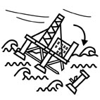
| Pictograph |
|
| Date |
March 27, 1980 |
| Place |
The North Sea |
| Location |
Ekofisk oilfield |
| Machinery |
Semi-submersible oil drilling platform
The offshore oil drilling rig, Alexander L. Kielland, is a semi-submersible platform supported by five columns standing on five 22 meter diameter pontoons (Fig.2). The dimensions of the platform are 103 x 99 meters in plan and 10,105 tons in weight. A 40 meter high drilling derrick and accommodations for 348 people were installed on the platform. The five 8.5 meter diameter columns on the pontoons were interconnected by a network of horizontal and diagonal bracings. The diameters of the horizontal and diagonal bracings are 2.6 m and 2.2 m, respectively. |
| Overview |
On March 27th, 1980, the semi-submersible platform Alexander Kielland suddenly capsized during a storm in the North Sea, because one of its five vertical columns supporting the platform was broken off. 123 workers among the 212 people on board were killed in the accident. The investigation showed that a fatigue crack had propagated from the double fillet weld near the hydrophone mounted to the tubular bracing D6. As a result, the five other tubular bracings connecting to the vertical column D broke off due to overload, and the column D became separated from the platform. Consequently, the platform became unbalanced and capsized. After the accident, the offshore design rules were revised and some countermeasures were added to maintain a reserve of buoyancy and stability for a platform under a storm. |
| Incident |
At around 6.30 pm on March 27th, 1980, the semi-submersible oil drilling platform "Alexander Kielland" capsized near the Norwegian Ekofisk oil field located at a latitude 56 degrees 28 minutes north and a longitude of 3 degrees 7 minutes (Fig.3), in a storm with window velocities from 16 to 20 m/s, temperatures of 4 to 6 C, and wave heights of 6 to 10 m, because the platform's columns broke off. Within seconds, the platform tilted between 35 and 45 degrees. After 30 minutes, the platform turned upside down (Fig.4). |
| Sequence |
The Alexander L. Kielland was designed as an oil drilling platform with a pentagon structure by France, and it was constructed from 1969 through 1977 by CFEM (Compagnie Francaise d'Enterprises Metalliques). The platform was delivered to Norway in July 1976. In 1978, the accommodation capacity of 80 was increased to 348. Annual inspections were mainly carried out for the columns and pontoons, and the inspection in September 1979 had passed. However the D6 bracing had not been included in the inspection. |
| Cause |
(1) Fracture features
A circular hole was introduced to the underside of the D6 bracing, and a pipe, which is called a hydrophone, was mounted into the circular hole by welding (Fig. 5). The hydrophone was 325 mm in diameter with a 26 mm wall thickness. The hydrophone was welded using a double fillet weld with a weld throat thickness of 6 mm. A drain of the bracing D6 had to be installed at a location 270 mm away from the hydrophone (Fig. 6).
As a result of examination of the welds of the D6 bracing, some cracks related to lamellar tearing were found in the heat affected zone (HAZ) of the weld around the hydrophone. However, no weld defects were found at any other location. Traces of paint coinciding with the paint used on the platform were recognized on the fracture surface of the fillet weld around the hydrophone in the bracing D6. These paint traces show that the cracks were already formed before the D6 bracing was painted. Examination of the fracture surface also showed that the fatigue cracks propagated from two initiation sites near the fillet weld of the hydrophone to the direction circumferential to the D6 bracing. Moreover, the fatigue fracture surface occupied more than 60% of the circumference of the D6 bracing (Fig. 7), and beach marks were formed on the fracture surface, which was about 60 to 100 mm away from the hydrophone. Striations with spacing of 0.25E-3 to 1.0 E-3 mm were observed in patches on the fracture surface of the D6 bracing.
(2) Characteristics of the welds of the hydrophone
Considering of the importance of the strength of the D6 bracing, welding of the drain into the bracing was carried out carefully according to the design rules. In the case of the installation of the hydrophone, however, a circular hole was made on the D6 bracing by gas cutting, and the surface of the hole was not treated by some process, such as a grinding. After cutting, a pipe, which was made by cold bending and welding using a plate with 20 mm thickness, was mounted into the hole of the bracing, and the pipe was attached by welded around the hole by double fillet welding with a throat thickness of 6 mm (Fig.8).
When the hydrophone was installed by welding, welding defects, such as incomplete penetration, slag inclusion, and root crack, were introduced in the welds, because of the poor gas cutting and welding. Moreover, lamellar tearing related to inclusions in the material used was found near the HAZ of the hydrophone. The stress concentration factor, Kt, of the fillet weld of the hydrophone was in the range of 2.5 to 3.0, which is higher than the average value of Kt of 1.6 for a fillet weld performed under normal conditions.
(3) Chemical composition and mechanical properties of materials
Specifications and results of analyses of the chemical composition of the fractured materials are shown in Table 1. The chemical composition of the materials was found to be within the specified limits. A comparison of the mechanical properties between the specification and the test results for the fractured materials is shown in Table 2. The yield strength of the D6 bracing in the longitudinal direction is slightly lower than the specified minimum values. In case of the hydrophone, the Charpy impact energy is lower than the required value of 39 J at -40 C. Moreover, the reduction of area of the hydrophone for the through-thickness direction is markedly reduced because of the large amount of inclusions.
(4) Stress on the D6 bracing
Considering the wind and wave data before the accident, the stress amplitude on the D6 bracing was estimated to be in the range of 131 to173 MPa. This result shows that the stress levels of the D6 bracing were relatively high as compared to the other horizontal bracing in the platform. The fatigue life of the D6 bracing with the hydrophone was calculated to be in the range of 0.7 to 5 years. |
| Response |
(1) Although the D6 bracing was one of primary components of the platform, little attention was given to the installation of the hydrophone into the bracing. Hence, a crack with a length of about 70 mm was introduced in the fillet weld around the hydrophone, before the D6 bracing was painted.
(2) Fatigue cracks propagated from two initiation sites near the fillet weld of the hydrophone in the direction circumferential to the D6 bracing at the early stage of the life of the platform.
(3) The five other bracings connected to the column D broke off due to overload, and the column D was separated from the platform. Consequently, the platform became unbalanced and capsized
(4) Inspection of the D6 bracing had not been carried out. |
| Countermeasures |
Based on the accident report, redundancies of stability and structural strength, and lifesaving equipment for the offshore oil drilling platforms were obligated by the Norwegian Maritime Directorate (NMD). Amendment of the MODU (Mobile Offshore Drilling Units) Code was carried out by the International Maritime Organization, and standards for stability, motion characteristics, maneuverability, watertight doors, and structural strength of the oil drilling platforms were strengthened. |
| Knowledge Comment |
Installation of attachments, such as the hydrophone, on a stressed component by welding often introduces a cause of fatigue failure. In order to improve the fatigue resilience of structures, it is important to avoid unnecessary welding and attachments. Attachments can reduce stressed components to the lowest design class. |
| Account of Concerned Parties |
A process engineer said that he heard two bangs while he was watching a film in the cinema. Within seconds, the platform tilted between 35 and 40 degrees, and all the lights went out. People in the cinema, which was filled to its capacity of about 40, were hurled across the room, and some of them were injured. All people rushed outside, but the survival suits and lifesaving boats equipped in the platform could not used because of the severe degree of tilt. |
| Scenario |
| Primary Scenario
|
Ignorance, Insufficient Knowledge, Poor Understanding, Production, Hardware Production, Shipping and Maritime, Offshore Oil Rig, Column, Bracing, Hydrophone, Failure, Fracture/Damage, Metal Fatigue, Welding and Join, Fracture of Welds, Usage, Maintenance/Repair, Inspection, Lacked Inspection, Crack Propagation, Failure, Large-Scale Damage, Capsize of Oil Rig
|
|
| Sources |
1) Norwegian Public Reports, The "Alexander L. Kielland" Accident, November, 1981, pp.1-472.
2) A,Almar-Naess, P. J. Haagensen, B. Lian, T. Moan, and T. Simonsen, Trans. ASME, Vol.106, March, 1984, pp.24-31.
3) S.Ishida, J. Naval Architecture and ocean Eng., No.734, 1990, pp.13-17, (in Japanese).
|
| Number of Deaths |
123 |
| Multimedia Files |
Fig_2.Alexander L. Kielland
|
|
Fig_3.Location of accident occurred
|
|
Fig_4.Process of capsize of Alexander L. Kielland
|
|
Fig_5.Position of hydrophone and bracings connected columns
|
|
Fig_6.Main fracture surface near hydrophone
|
|
Fig_7.Fracture feature of D6 bracing
|
|
Fig_8.Dimensions of hydrophone
|
|
Table_1.Chemical composition of D6 bracing and hydrophone
|
|
Table_2.Mechanical properties of D6 bracing and hydrophone
|
| Field |
Material Science
|
| Author |
KITUNAI, Yoshio (Japan Crane Association)
KOBAYASHI, Hideo (Yokohama National University)
|
|