| Case Name |
Burst of Steam Turbine Rotor in Fossil Power Plant |
| Pictograph |
|
| Date |
June 19, 1974 |
| Place |
Gallatin, Tennessee, USA |
| Location |
the Tennessee Valley Authority ,the Gallatin No.2 |
| Machinery |
The burst component was an IP-LP turbine rotor made of a Cr-Mo-V steel (ASTM A470, Class8). The rotor was forged from an air melted ingot in 1954, followed by austenitization heat treatment conducted at 955°C. The unit was base loaded at 225MW from May 1957. The steam conditions of the burst rotor were 13.8MPa and 566°C, and its rotation speed was 3,600rpm. |
| Overview |
An intermediate pressure (IP) - low pressure (LP) steam turbine rotor of the Gallatin No.2 unit in the Tennessee Valley Authority (TVA), which was located in the center of the State of Tennessee, USA, experienced a brittle fracture at about 3,400 rpm during a cold start on June 19th, 1974 after 106,000 hours of service. Consequently, the rotor fractured into dozens of pieces, and some of the pieces flew off to hit a boiler building. Unfortunately, at the time, a pre-service boresonic inspection¹); was not required for this rotor, and thus the rotor had been kept under service operation without noticing the existence of a large cluster of manganese sulfides (MnS) that had become segregated near its bore. A creep-fatigue crack growing from the MnS cluster combined with temper embrittlement due to its long-term service led to the burst of the IP-LP rotor. In response to this accident, US electric power companies conducted boresonic inspections of all of their own rotors. Also, the Electric Power Research Institute (EPRI) developed the SAFER (Stress And Fracture Evaluation of Rotors) code for deciding whether to run or retire a steam turbine rotor, and the code was employed for the operation management of rotors. This accident caused a big shock in the USA and other countries. Also, the accident gave us many lessons (e.g., the requirement for nondestructive evaluation methods) and resulted in a worldwide advance in steam turbine technology. Therefore, this accident can be considered as one of the most significant accidents resulting in valuable knowledge and lessons that were transferred to future generations.
1)Note : boresonic inspection = ultrasonic inspection conducted to the inside of a bore |
| Incident |
On June 19th, 1974 during a cold start after a long shutdown for repairing the TVA Gallatin No.2 unit, the IP-LP rotor burst at approximately 3,400rpm. The rotor had been in operation for 106,000 hours from its operational start in May 1957 (see Fig.1).
The following paragraphs describe the results from Fault Tree Analysis.
(1) Fault tree diagram for mode, mechanism and process of fracture (Fig.2)
The burst rotor forged from an air melted ingot in the 1950's had a MnS segregation zone near its bore. However, at that time, the pre-service boresonic inspection was not required for the rotors austenitized at 955°C. Thus, its service operation was continued for over 100,000 hours without noticing the existence of the MnS segregation zone, which resulted in crack growth due to creep-fatigue interaction. Also, temper embrittlement occurred over the long period of operation. Therefore, the rotor burst by brittle fracture during a cold start after a long shutdown for repair.
(2) Fault tree diagram for design and manufacturing errors (Fig.3)
At that time, the pre-service boresonic inspection was required only for the steam turbine rotors made of a Cr-Mo-V steel that had been austenitized at 1100°C. Because the austenitization temperature of the rotor was 955°C, the pre-service boresonic inspection was not conducted. As a result, the rotor was operated for a long period without noticing the existence of a large MnS cluster that had become segregated near the bore during ingot manufacturing. This MnS cluster caused the burst accident.
(3) Event tree diagram for the steam turbine rotor burst attributed to the lack of the requirement for the pre-service boresonic inspection (Fig.4)
The existence of a MnS segregation zone near the bore of the rotor forged from an air melted ingot of a Cr-Mo-V steel was not detected because the pre-service boresonic inspection was not required for rotors that were austenitized at 955°C. The long-term operation of the rotor having a big flaw of MnS inclusions near its bore resulted in creep-fatigue crack initiation and propagation from the flaw. Finally, a brittle fracture during a cold start was caused by the crack growth in combination with the temper embrittlement that had resulted from the long period of operation. |
| Sequence |
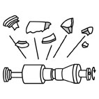
The burst rotor forged from an air melted ingot in the 1950's had a MnS segregation zone near its bore. At that time, the pre-service boresonic inspection was required only for the steam turbine rotors made of a Cr-Mo-V steel that had been austenitized at 1100°C. Because the austenitization temperature of the rotor was only 955°C, the pre-service boresonic inspection was not conducted. Consequently, the service operation of the rotor was continued for over 100,000 hours prior to the burst accident without noticing the existence of the MnS segregation zone (Fig.5). As shown in Fig.6, a crack grew due to creep-fatigue interaction during the operation period. Also, the rotor material was degraded by the temper embrittlement that occurred during the long period of operation. Consequently, the brittle fracture of the rotor during a cold start was caused by the superposition of mechanical damage and material degradation. Finally, the rotor fractured into thirty large pieces, and some of the pieces flew off to a hit boiler building. |
| Cause |
The pre-service boresonic inspection was required for rotors that had undergone austenitization treatment at 1100°C which had previously experienced some accidents. However, the inspection was not required for rotors in which the temperature of the austenitization treatment was shifted to 955°C as a countermeasure to the previous accidents. If the inspection had been required for all rotors, the burst accident could have been avoided because the large MnS segregation zone of the rotor would have been detectable by the pre-service inspection. |
| Response |
(1) The pre-service boresonic inspection was made mandatory for all rotors after this accident. In particular, inclusions such as MnS segregated easily in the middle part of air melted Cr-Mo-V steel ingots that had been manufactured in the 1950's. Previously, a bore had been machined into the center of a rotor to locate and remove the inclusions. However, it is difficult to remove inclusions perfectly as seen in this accident. Therefore, the pre-service boresonic inspection is essential for improving the reliability of rotors.
(2) In the case of a hollow rotor with a bore, the tangential stress due to centrifugal force is the largest at its bore surface. On the other hand, in the case of a solid rotor without a bore, the maximum tangential stress is in the center of the rotor, and its value is smaller than that in a hollow rotor. For example, for a rotor with a very small bore diameter, the maximum tangential stress in a solid rotor is half the value in a hollow rotor as shown below. Therefore, a solid rotor in which the maximum stress is smaller has an advantage with respect to creep damage. Improvements in steel manufacturing technology since the age of air melting include the development and application of new techniques such as vacuum melting. Recently, solid rotors are available with reduced amounts of inclusions as a result of the high quality forging process.
The maximum stress applied in a rotating cylinder such as a rotor is shown as follows:
(a) Rotating hollow cylinder
The tangential stress σ θ is the highest on its inner surface as expressed by the following equation.
(1)
where, ra is the inside radius, rb is the outer radius, γ is the specific weight, ω is the angular velocity (constant) , g is the acceleration of gravity, and ν is the Poissson's ratio. When ra → 0 in Eq.(1), the following equation can be obtained.
(2)
(b) Rotating solid cylinder
Both the tangential σ θ and the radial stress σ γ are the highest in its center as expressed by the following equation.
(3)
Comparing the maximum stresses given by Eqs. (2) and (3), (σ θ)max in the rotating solid cylinder is found to be half the value of that in the rotating hollow cylinder. |
| Countermeasures |
All electric power companies conducted the following countermeasures immediately after the accident:
(1) Rotor replacement based on the results of boresonic inspection
(2) Requirement of boresonic inspections for all rotors
After several years of R&D following the accident, EPRI introduced the following countermeasure:
(1) Development of the SAFER code in EPRI and use of the code in electric power companies for the decision of Run/Retire for a rotor
Manufacturers have conducted the following countermeasures based on the results of technological progress after the accident, although they have no direct relation with the accident:
(1) Development and application of vacuum melting process
(2) Development and application of a solid rotor |
| Knowledge Comment |
"The nondestructive evaluations should definitely be required, even if there is no firm technical reason for the evaluation." |
| Scenario |
| Primary Scenario
|
Misjudgment, Narrow Outlook, Poor Guidelines, Planning and Design, Poor Planning, No Inspection, Steam Turbine Rotor, Air Melted Cr-Mo-V Steel Forging, Bore, Oversight of MnS Segregation, Usage, Operation/Use, Operation of Machine, Failure, Fracture/Damage, Creep-Fatigue, Crack, Burst of Rotor
|
|
| Sources |
(1)L.D.Kramer and D.Randolph, "Analysis of TVA Gallatin No.2 Rotor Burst : Part 1-Metallurgical Considerations," Proc. 1976 ASME-MPC Symposium on Creep-Fatigue Interaction, pp.1-24(1976).
(2)D.A.Weisz, "Analysis of TVA Gallatin No.2 Rotor Burst : Part 2-Mechanical Analsis," Proc. 1976 ASME-MPC Symposium on Creep-Fatigue Interaction, pp.25-40(1976).
|
| Multimedia Files |
Fig_2.Overview of the burst TVA Gallatin No.2 IP-LP turbine rotor
|
|
Fig_3.Fault tree diagram for mode, mechanism and process of fracture
|
|
Fig_4.Fault tree diagram for design and manufacturing errors
|
|
Fig_5.Event tree diagram for the steam turbine rotor burst attributed to not requiring the pre-service bore sonic inspection
|
|
Fig_6.MnS segregation zone existing near bore
|
|
Fig_7.Crack growth by creep-fatigue interaction from MnSs.
|
|
Fig_8.Thermal fatigue crack initiating at the heat groove of HP turbine rot
|
| Field |
Material Science
|
| Author |
NITTA, Akito (Central Research Institute of Electric Power Industries)
KOBAYASHI, Hideo (Yokohama National University)
|
|