| Case Name |
Gas Explosion at a Subway Construction Site |
| Pictograph |
|
| Date |
April 8, 1970 |
| Place |
Osaka City, Osaka Pref. |
| Location |
Construction site of subway |
| Machinery |
Gas piping |
| Overview |
On April 8th, 1970, a huge gas explosion occurred at the site of construction for elongation of Osaka city subway line No.2 (Tanimachi line). The gas was leaked out of a detached joint for a drainer on the medium pressure piping, which was under construction for suspension. The gas was filled in the tunnel, ignited, and exploded violently creating a fire pillar of over 10m in height, and causing cover plates over to scatter over an area 200m in length (Figures 2, 3, and 4). The explosion resulted in a terrible accident (so-called Tenroku gas explosion accident), with 79 persons dead, 420 persons injured and 495 houses and buildings burned and destroyed. Almost all of the victims were bystanders having no direct relation to the construction work. The causes of the accident were believed to be a decrease of the joint strength by the weight of passing traffic vehicles together with the influences of the construction work itself. Furthermore, no measures were taken against drawing off the joints. Because most of victims were bystanders, this accident had a large social influence, and it left various precepts as a municipal disaster that was produced by the tremendous boom of municipal development in an age of high economic growth. |
| Incident |
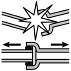
At the site of construction for elongation of Osaka city subway line No.2 (Tanimachi line), the suspending work had been conducted in the underground for the exposed pipes of medium and low pressure gas (Figures 5 and 6). A joint of the drainer for the medium pressure pipe became detached, and that caused gas to blow out, ignite, and then explode violently (Figure 7).
Results of fault tree analysis are described below.
Figure 8 - Fault tree diagram based on morphology, mechanism, and process of the destruction.
The possible causes of the gas leak are considered to be rupture, draw out, crack, or opening of the pipe. Results of investigation after the accident showed that a joint of the drainer for the medium pressure pipe was drawn down, and that was assumed to cause the leak of gas.
The same type of the drawn joint had an initial strength that was rated against an inner pressure of about 8 tons, however, the detached joint could not resist an inner pressure of even 1 ton. The cause of this change in the strength of the joint could be one or more of the following; (1) the strength of the joint had decreased, (2) no measure was taken to prevent the drawing off the joints, and (3) the construction work on the day of the accident formed a suspending condition of the pipe. These complex conditions caused the drawing down of the joint of the pipe.
Cause (1) of the decrease in strength of the joint was considered to be the result of the following three factors, initial defects, gradual degradation over time by the traffic load, and influences from the construction work of the subway. The possibility of initial defects that were formed when the joint buried under the ground, was estimated by considering the working situation and procedure of the burying process as well as the burying conditions at that time. The gradual degradation of the joint strength was considered to be important because of the shallow depth at which he medium pressure gas pipe was buried that caused it to suffer from vibration and subsidence by the passing traffic vehicles prior to the start of the construction work on the subway. After beginning the subway construction work, repeated excavation and burying in the area for the experimental drilling and covering was estimated to exert a larger influence than the traffic loads even though the period was much shorter.
The source of the ignition was regarded at first to be an emergency vehicle, which caught fire at the site of the gas leakage. However, because the fire of the emergency vehicle continued for about ten minutes, the concentration of the gas mixture in the upper part of the pit just below the fire was believed to have already exceeded the limit of combustion, so that there was no fear of catching fire. Otherwise, the fire in the emergency vehicle should have occurred at the same time as the ignition of the explosion. The explosion occurred at near the center where the emergency vehicle that had caught fire located. However, the ignition point does not always coincide with the center of explosion because of a phenomenon by which the flame caused by the ignition propagates in the mixed gas before the explosion. From the reasons mentioned above, it is difficult to consider that the emergency vehicle fire was the source of ignition. There were many other potential sources of ignition around the site. The ignition source was considered to be one of those other potential sources except the emergency vehicle.
Results of event tree analysis are described below.
Figure 9 - Event tree diagram for the explosion and the leak of gas by drawing off the joint.
The fastening strength of the gas pipe was decreased by an initial defect that had occurred immediately after the burying work. Furthermore, the joint strength degraded gradually over time from vibration and subsidence caused by the traffic loads, and finally the joint strength decreased rapidly as a result of the influences of the subway construction work. The pipe was exposed in hanging condition during the construction work. The decreased joint strength could not resist the inner pressure because there was no prevention against drawing off. Then the joint was drawn off, and caused the gas leak. The explosion occurred as a result of some unidentified ignition source. |
| Sequence |
The medium pressure gas pipe, the joint of which was drawn off in the accident was installed in May 1957.
The construction work of the subway was conducted by the open-cut method, one of the methods for digging tunnels. The procedure of the open-cut method is as follows. First, steel piles are hammered along both sides to form walls. Then, the steel piles are bridged with H-shaped steel bars, upon which covering plates are placed to minimize the traffic disturbance on the roads. Finally, the area between the walls of steel piles is excavated from the ground surface. In this construction work, a tunnel of 11m in width, 5m in depth, and 225m in length was excavated along the north side of a road of 26m in width, and covered with covering plates (2m in length, 75cm in width, 20cm in thickness, and 380kg by weight) which were made of concreted steel frames.
The gas pipe, a total of 200 m in length, had two traversing points at both ends forming right angles bends. On the morning of April 8, the soil under the north corner of the traversing point was removed causing the entire length of the medium pressure gas pipe including the traversing points to be suspended, making it easy for pipe to move near the traversing point in a horizontal direction.
At about 5:15 pm, 27 workers under suspending work for the exposed pipes escaped from the tunnel to the surface because they noticed the gas that blew out suddenly. At 5:20 pm, a patrol car of the gas company, on the way back to the base by chance, also found the gas leak by chance, and took communications by wireless with an emergency car and a repair car to call out. Fire trucks also arrived by dispatch from stations around the site. At that time, the gas blew out from cracks, 20m in length, between the cover plates. Fire men requested all residents and bystanders in the area to evacuate and avoid using fire. At 5:39 pm, when the emergency car of the gas company started its engine over the cover plates, the car caught fire, and then the gas blowing from the cracks also ignited. The fire gained force gradually, and at 5:47 pm, a huge explosion with a fire pillar of over 10m in height occurred, causing the cover plates to scatter over an area 200m in length. The injured persons and the cover plates fell down to the ground, and the fire pillar expanded to the surrounding houses on both sides. |
| Cause |
The strength of the joint had decreased by multiple causes including initial defects, gradual degradation with traffic loads, and influences from the construction work for subway. Construction work related personnel should have estimated the decrease of the joint strength, even though the failure may not been anticipated. Therefore, the basic cause of the accident was attributed to the lack of measures taken to prevent the drawing off of the joints. |
| Response |
When a large gas leak happens, construction work related personnel must inform not only the gas company, but also the fire station and the police station. Depending on the place and situation of the gas leak, the personnel must announce to persons in a wide area that persons and cars are not to enter the site and they must inform people around the site that the use of fire is prohibited as soon as possible. Furthermore, they must order the neighboring residents to take refuge in a safety area.
The victims of this accident included a crowd of curious spectators for the first gas leakage, who did not realize that they were standing on the cover plates. In order to avoid such a tragedy, persons around the site must be ordered to take refuge in a safety area. |
| Countermeasures |
Taking opportunity of the accident, the Gas Service Act, 77th and 78th articles, "Protection of gas pipe exposed by excavating" was legislated. The act contained the following stipulations.
> Confirm that sand and soil at both ends of an exposed pipe have no possibility of collapse.
> Take suitable measures to prevent leakage.
> Take measures to absorb and to disperse the expansion and contraction of the pipe by the change of temperature.
> Take measures to shut off the gas in an emergency. |
| Knowledge Comment |
> Consider the possibility of defects:
This accident occurred because of no one had considered the possibility of a defect causing the decrease of joint strength. Construction work related personnel should take actions based on consideration that old facilities used for a long time might have some number of defects. It should be remarked that routine actions considered to be safe in ordinary circumstances might in fact be quite dangerous unknown to anyone.
> Recognize the dreadfulness of urban civil engineering works. |
| Sequel |
In regard to the criminal responsibility of the accident, the accused side, that is, the constructor, Osaka-city, and Osaka Gas Company, was tried with the procurator side in criminal court. The judicial decision, given fourteen years later, judged a responsibility of negligence on the part of the accused side. At that time, a series of judgments of "not guilty" had continued in the criminal trials on urban disasters. This judgment changed the trend of criminal trial and became an epoch-making decision to recognize anew the importance of safety.
The judgment concluded that the accident was the joint responsibility of the accused three juridical persons for not applying an appropriate preventive draw off measure that would have been an effective method for preventing the accident. |
| Scenario |
| Primary Scenario
|
Poor Value Perception, Poor Safety Awareness, Lack of Safety Measure, Organizational Problems, Poor Management, Poor Management for Work, Production, Hardware Production, Construction Work for Subway, Open-cut method, Suspension of Gas Pipe, Regular Operation, Nonobservance of Procedure, No prevention against Drawing Off, Malfunction, Poor Hardware, Decrease of Joint Strength, Failure, Fracture/Damage, Drawn Off Joint for Drainer, Secondary Damage, External Damage, Leak of Gas, Explosion, Bodily Harm, Death, Bodily Harm, Injury, Damage to Society, Social Systems Failure, Burned Down of Houses
|
|
| Sources |
(1)On the Liaison Office for Accident of Gas Explosion at Osaka, May, 1970, Gas Section, Department of Public Utility service, MITI.
(2)Information about Cases of Serious Accidents, The Japan Gas Association.
|
| Number of Deaths |
79 |
| Number of Injuries |
420 |
| Physical Damage |
495 of houses were burned down or damaged |
| Financial Cost |
Unclear |
| Economic Loss |
Unclear |
| Multimedia Files |
Fig_2.Spot of gas explosion accident.
|
|
Fig_3.Appearance of fire by gas explosion.
|
|
Fig_4.Rough sketch of accident spot.
|
|
Fig_5.Appearance of piping for city gas.
|
|
Fig_6.Imaging sketch of hanging situation.
|
|
Fig_7.Connecting method for piping.
|
|
Fig_8.Fault tree diagram based on morphology, mechanism, and process of the destruction.
|
|
Fig_9.Event tree diagram for the explosion and the leak of gas by drawing off the joint.
|
| Field |
Material Science
|
| Author |
AKATSUKA, Hirotaka (High Pressure Gas Safety Institute of Japan)
KOBAYASHI, Hideo (Yokohama National University)
|
|