| Case Name |
Leakage of Sodium Coolant from Secondary Cooling Loopin Prototype Fast Breeder Reactor MONJU |
| Pictograph |
|
| Date |
December 8, 1995 |
| Place |
Tsuruga, Fukui pref. |
| Location |
MONJU, of Power Reactor and Nuclear Fuel Development Corporation (PNC) |
| Machinery |
Terminal of the thermometer sensor on the outlet piping of the secondary main cooling loop in the intermediate heat exchanger. |
| Overview |
On December 8, 1995, a leakage of sodium coolant occurred at the terminal of the thermometer sensor on the secondary sodium cooling loop in the prototype fast breeder reactor MONJU, of Power Reactor and Nuclear Fuel Development Corporation (PNC) in Tsuruga city. The leakage resulted from the break of the thermometer well caused by fatigue due to the fluid vibration. The reactor was stopped manually in response to the alarm of sodium leakage, and the sodium in the loop pipe was fed back to the sodium tank.
The fatigue fracture was attributed to a defective design standard of the thermometer well that had specified that the vibration by cyclic vortex should be evaluated only in the direction perpendicular to the flow. |
| Incident |
Results of fault-tree analysis are as follows;
Figure 3.- Fault-tree diagram based on morphology, mechanism, and process of fracture. Leakage of sodium occurred as a result of a break in the thermometer well. The break point corresponded to a part of the thermometer well where its diameter had been sharply changed. Investigation and observation of the fracture surface confirmed the cause of the break to be a high frequency fatigue due to fluid vibration in the direction parallel to the flow. The direction of the fatigue crack propagation coincided to that of the sodium flow, which had caused the well to vibrate in a direction parallel to the flow. The flow-induced vibration was, therefore, clarified due to a symmetrical vortex.
Figure 4 - Fault-tree diagram based on defective design standard and fabrication of equipment.Because of a mistake in the design standard, the designer had evaluated only the vibration in the direction perpendicular to the flow that is caused by an alternative vortex. In addition, the shape of the well had been designed to have a part where the diameter changed sharply, and a stress concentration was induced at the region of diameter change that caused the fatigue crack.
Results of event-tree analysis are as follows
Figure 6 - Event-tree diagram on the break of the thermometer-well caused by a flow-induced vibration due to a symmetrical vortex. There are two kinds of flow-induced vibrations that are induced by Karman's vortex row: a vibration in the direction perpendicular to the flow caused by an alternative vortex, and a vibration in the direction parallel to the flow caused by a symmetrical vortex. The relation between the amplitude and flow rate in vibration of the thermometer well is shown in Figure 7. Based on the defective design standard, the designer had evaluated only the former perpendicular vibration in the design of the thermometer well, not the later parallel vibration. However, the vibration in the direction parallel to the flow that was caused by the symmetrical vortex resulted in a high frequency fatigue fracture in the well due to the resonance and the stress concentration. The resulting break in the well caused the leakage of sodium. |
| Sequence |
On December 8, 1995, the nuclear reactor Monju was operated in raising power for the plant trip test, as a part of the 40% output test. At 18:47, an alarm was triggered that indicated a higher than normal temperature of the sodium at the outlet of the intermediate heat exchanger in the secondary loop C. At the same time, the fire alarm was also sounded. After one minute, an alarm indicating a leak of sodium in the secondary main loop C was also triggered. In response to the alarms, operators opened the door of the secondary main loop C pipe work room, where they observed smoke, in the expansion of the fire alarm. They decided that the smoke and alarms were caused by a leak of sodium, so they tripped the reactor manually at 21:20 and drained the sodium that was in the pipe to the stock tank. An investigation in the pipe work room C confirmed the leak of sodium from the terminal of the thermometer in the outlet piping of the secondary main cooling system for the intermediate heat exchanger. |
| Cause |
(1) Defective design standard
The recommended practice for preventing vibration due to Karman's vortex row was introduced into the design standards for _____ decades ago. In 1974, the ASME(American Society of Mechanical Engineers) Standard, which is widely used all over the world, provided the following regulation about the vibration in the direction perpendicular to the flow caused by an alternative vortex: ASME Performance Test Code, Supplement on Instruments and Apparatus Part 3, Temperature Measurements, 1974.
(Frequency of vortex row) < 0.8 x (Frequency of proper vibration for cylinder)
In addition, ASME added a supplementary regulation about the vibration parallel to the flow caused by the symmetrical vortex: ASME Boiler and Pressure Vessel Code, Section III, Division 1, Appendix N-1300, Flow-induced vibration of tubes and tube-banks, 1995.
(Velocity of flow) / (Diameter of cylinder) < (Frequency of proper vibration for cylinder)
In the Japanese version of the standards, the additional regulation about the vibration parallel to the flow failed to be noticed.
(2) Thermometer well with a sharply changing step-wise diameter
Stress concentration at the point where the diameter of the well changed sharply in a step-wise caused the fatigue crack fracture. In order to reduce the stress concentration, it is necessary to take a large radius of curvature at the changing point of the well's diameter. Inspection for the design with the step-wise shaped thermometer well was insufficient |
| Response |
(1) It was confirmed that the technical information system would be kept up-to-date, and the newest design standards were consolidated.
(2) The method for examination of the design was improved in order to strengthen the design management, and the outline of the design process was rechecked. |
| Countermeasures |
The design standards should be periodically reexamined and updated with the newest technical information. In 1997, the PNC established a design guideline for preventing the flow-induced vibration of the thermometer (PNC TN9410-97-042). Based on this guideline, the Japan Society of Mechanical Engineers established the guideline for evaluating the flow-induced vibration of a cylindrical structure on piping (JSME S 012-1998) in 1998. |
| Knowledge Comment |
Mismatching among specialist fields;
The technical specialists designing the structure of a plant such as the Monju belong to three fields of expertise, that is, materials and strength, thermal fluid flow, and vibration. Each specialist restricts his or her job and area of responsibility to that specialist's own field of expertise. In particular, the specialist fails to make the effort to develop a mutual understanding and exchange of information with specialists from other fields. The mismatching between the specialist fields is an important cause of accidents, such as the one described here. A typical example of the importance of collaboration between different specialist fields is the evaluation of fatigue fractures due to flow-induced vibration versus those due to thermal stress. |
| Sequel |
A vortex is defined as the motion of a fluid to rotate. There are various kinds of vortices. When a spoon stirs water in a cup, vortices are formed behind the spoon. In the case of airplanes and motor vehicles, vortices of air are formed behind their bodies in the same way. Smoke from a chimney or cigarette smoke from a human mouth forms a ring-shaped vortex. The rotation of the screw of a ship forms a spiral vortex. A row of vortices is the source of the fluid vibration.
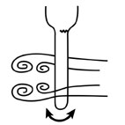
If a physical solid, for example a cylindrical rod, exists in a flowing fluid, vortices are formed behind the solid. The same phenomenon occurs when the solid moves in a static fluid. A row of the vortices is most easily formed if the solid has a shape that is symmetric to the flowing direction and that does not have any sharp point at the rear, such as that of a cylindrical rod (a cylindrical pole).
Behind a cylindrical rod, if the first vortex is formed on the right hand side, the second one will be formed on the left, and the next one on the right, and so on, alternating between left and right. The direction of the vortices in the row on the right hand side is the opposite of that on the left. The vortices of the two rows occur at even intervals, but rather than being aligned, the vortices on the left and right are arranged in a zigzag fashion. The reason for why this phenomenon occurs was first elucidated theoretically by Th. von Karman, so that this phenomenon is called Karman's vortex row.
If velocity of the fluid is V (m/sec) and the diameter of the cylindrical rod is D (m), the number of vortices f (sec-1=Hz) generated per second can be roughly estimated by the following equation:
f = 0.2 V/D
The vortices generated on the left and right are asymmetrical, so the distribution in the velocity of flow is different on the left and on the right. The different distributions of velocity cause different distributions of the hydraulic pressure (Bernoulli's theorem), so that a composite force is generated by hydraulic pressure in the direction perpendicular to the flow. Alternative vortices on the left and right cause the alternative composed forces by hydraulic pressure, so that a vibrating force having the same frequency f (Hz) acts on the solid. The solid vibrates in the direction perpendicular to the flow (left and right); that vibration is called the fluid vibration. Because there is also a difference in the distribution in flow velocity in front of the solid and behind the solid, the solid also vibrates in the direction parallel to the flow. The trembling of reeds in a river is caused not always by the wind but also by the fluid vibration, especially in the case of the shaking of the heads of the reeds. Fluid vibration causes damage in the form of noise and fatigue. A vibrating bamboo rod makes a sound. High tension wires make sound as a result of vibrations induced by the wind. The boughs and twigs of trees shriek (WAIL?) violently in a typhoon. A twig with a diameter D=5 mm vibrates at f=400Hz in response to a strong wind of V=10m/sec, causing a wave of air (an acoustic wave, sound) to vibrate the human eardrum, making a gentle sound. A typhoon wind of V=30m/sec makes a shrieking sound of f=1200Hz. The frequency given by a row of vortices coincides with the proper frequency of the solid to produce resonance and to generate a strong sound. This is the same principle that causes the strings of a kite to groan (MOAN?). A solid experiencing sympathetic vibration suffers from fatigue and failure easily.
Damage from fluid vibration occurs in high tension wires, chimney stacks, the supports of a bridge, hydraulic turbines, pumps, the screw of a ship, and the periscope of a submarine. The fundamental countermeasure is to avoid the sympathetic vibration that gives rise to resonance, by raising the frequency of the proper vibration of the solid over the frequency of the row of vortices. A large diamter raises the former, and lowers the latter, so increasing the diameter of the solid is a simple solution. Another solution is to break the row of vortices by changing the shape of the solid, such as winding a rope around a cylindrical pole, attaching a fin at the rear of the solid, streamlining the cross sectional shape, and so on. |
| Incidental Discussion |
*********************** Refer to 100 Selected Cases. ************************** |
| Scenario |
| Primary Scenario
|
Misjudgment, Narrow Outlook, Lacked Standard, Planning and Design, Poor Planning, Bad Design, Thermometer Well, Bad Event, Thermo-Fluid Event, Fluid Event, Fluid Vibration, Karman's Vortex, Vibration Parallel to Flow, Failure, Fracture/Damage, Fatigue, Crack, Penetrate through Wall Thickness, Leak of Sodium
|
|
| Sources |
(1) Materials in Research committee to utilize fault knowledge (No.4), Leak of sodium from secondary loop in prototype fast breeder reactor MONJU, Power Reactor and Nuclear Fuel Cycle Development Corporation, December 12, 2000.
(2) Hideo Kobayashi: Fluid Vibration, High Pressure Gas, 33-9(1996), 755.
(3) Hideo Kobayashi: Fluid Vibration Fatigue, High Pressure Gas, 33-11(1996), 950-951.
|
| Number of Deaths |
0 |
| Number of Injuries |
0 |
| Multimedia Files |
Fig_2.Schematic diagram of reactor
|
|
Fig_3.Appearance of leakage point of sodium
|
|
Fig_4.Broken thermometer well and leakage route of sodium
|
|
Fig_5.Fault-tree diagram based on morphology, mechanism, and process of fracture.
|
|
Fig_6.Fault-tree diagram based on wrong design and fabrication of equipments
|
|
Fig_7.Event-tree diagram on the break of thermometer-well caused by a flow-induced vibration due to a symmetrical vortex
|
|
Fig_8.fig
|
|
Fig_9.fig
|
|
Fig_10.fig
|
|
Fig_11.fig
|
| Field |
Material Science
|
| Author |
KOBAYASHI, Hideo (Yokohama National University)
|
|